Report for Maintenance Air Cooled Chiller Power Ciat 2800X
Rasheed N. Abed1* and Ramzi Qasim Muhammed2
1Mechanical Engineering Department, Engineering College, Al-Nahrain University, Jadriah, 64040 Baghdad Iraq .
2Nanorenewable Energy Research Center, Al-Nahrain University, Baghdad Iraq .
http://dx.doi.org/10.13005/OJPS04.02.04
Copy the following to cite this article:
Abed R. N, Muhammed R. Q. Report for Maintenance Air Cooled Chiller Power Ciat 2800X. Oriental Jornal of Physical Sciences 2019; 4(2). DOI:http://dx.doi.org/10.13005/OJPS04.02.04
Copy the following to cite this URL:
Abed R. N, Muhammed R. Q. Report for Maintenance Air Cooled Chiller Power Ciat 2800X. Oriental Jornal of Physical Sciences 2019; 4(2). Available From : https://bit.ly/3vWEO13
Download article (pdf) Citation Manager Publish History
Introduction
Chillers are great equipment vastly used to supply air-conditioning of buildings, government offices, commercial markets, hotels, hospitals, and flats in buildings. These chillers are consumed energy to produce cooling capacity for these above divisions. Not overstated to talk, overhead a half of the consumption of electricity in buildings is utilized by chillers and correlated equipment. Air-cooled or water-cooled chillers are depended upon many parameters such as: a set of water temperatures, the performance of the chiller when working at a part-load, types of compressors used, types of refrigerant that used, the temperatures of the water entering the condenser or cooling tower, ambient temperature, single or multiple units which operated together, and the conditions of the maintenance. The idea which is used to cool computerize center was much activated and utilizes as the first time in this place.1
Moreover, chillers are permanently operating in part load when the ambient temperature is ranged between (35-38 oC), but whenever the ambient temperature is raised to (45 oC) running at full load. It is necessary, the performance of the chiller for giving the buildings a full cooling load depending upon the ambient temperature and regarded a significant factor of work these chillers at maximum load. Then the choice of chiller has many limitations in representing the actual chiller performance under diverse operation and climate conditions. Indeed, the issues of chillers are determined to carry out a comprehensive analysis which reflects the actual weather data and the material that construction the buildings.2
Therefore, chiller efficiency is affected by many factors such as: properties of the material of buildings, operating hours, and the shading of buildings from the solar radiation. When the designer has the best understanding of the overall performance of the chiller working, this let to select a chiller has the cooling load capacity for the buildings. In addition to the specifications of the chiller, it includes more capital cost and more spacious area for installation, for all those associated equipment such as the electrical power supply from electrical equipment and cables, piping system, air handling units, and chilled water pumps. According to records, the ambient outdoor temperature limits during the operation of the unit are as follows is ranged between (35-55 °C) in summer for air-cooled chiller, but the condenser water temperature is typically ranged between (24 °C to 38 °C) in the summer for water-cooled chiller. As well as, must be maintained on the chilled water temperature at (7 oC) above the set point for the chiller that is at (5 °C) to prevent evaporator freezing of the chiller. Chiller ciat is the one that was used in the Presidency building of Al-Nahrain University to feed a cooling in all offices for this building and student club building.3 The chiller unit consisted of the major units: a two Screw compressor has cooling capacity was (200 tons of refrigeration), twelve outdoor fans to cool the condenser, CPU microcontroller to operate the chiller and the microprocessor. The coefficient of performance (COP) of chiller ciat in full load is (4.15) to exhibit the best chiller for cooling under the design conditions.4
The electronic control module of the microprocessor with display for air-cooled chillers is supplied as a type of water chiller equipped with screw compressors with two refrigeration circuits. By depending on the formation, the plate provides the following features:
- Control of the chilled water or hot water temperatures.
- Continuous observation of operating information.
- Diagnostics and fault storage to show the information through the display screen.
- Setpoint for the parameters based on the outdoor air temperature in cooling mode.
- The communicated with the console and the operating boards for following the fault reporting and repaired.5
In this report will exhibit the problems which are led to fault the chiller ciat has 200 tons of refrigeration to produce a cooling load of the presidency of Al-Nahrain University building, and the package ciat also has a 15 ton of refrigeration which feeds cooling to the computerize center in the student club building. Therefore, the central air conditioning was repaired of the chiller ciat and stand on these problems of the two systems that transfer the chilled water to the air handling units, and pump system to pump the chilled water, CPU microcontroller, outdoor fans of the condenser for chiller and package, coils of the chillers and package, and screw compressor for the chiller and scroll compressor for the package unit.
Features of Chiller and Package Ciat
Chiller ciat layout to demonstrate the chiller details specifications as shown in figure (1), this figure exhibit the detail about the ciat chiller 2800 X with its dimension and the body of the chiller that consist of the screw compressor, condenser fans, condensers, and all connected pipes.4
 |
Figure 1: chiller ciat layout with all specifications7 Click here to view Figure |
Chiller is operated by using the console screen and the buttons which included with the screen as shown in the figure (2), all these buttons are used to operate and setting of the chiller. The cooling fluid was Freon R-134A as a refrigerant to cool the water in the evaporator. This screen consists of LCD (2 lines of 20 characters) to let the available free contacts inputs information as: flow rate sensor, set point 1 or 2 selection for the circuit running, general fault, pump control, load shedding for compressors, and emergency cut. The screen is worked as a remote control for chiller and its electrical current about (4-20 mA). Outputs information as: general fault per circuit, fault information contact, hot gas discharge temperature, superheating and de-superheating temperature, antifreeze temperature fault, and fans fault.6
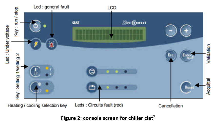 |
Figure 2: console screen for chiller ciat7 Click here to view Figure |
Package ciat RPF 180U is shown in figure (3), 45.1 kW, 12.5 tons, and 5000 cfm (ft3/m). The rooftop package unit is consisted of a centrifugal fan to cool the condenser and axial fan to supply the cool air which enters to the offices rooms, hermetic scroll compressors, control board, condenser coil and evaporator coil contains a Freon R-410A as a working refrigerant to cool the air that enters to the evaporator.7
 |
Figure 3: package ciat picture RPF 180U8 Click here to view Figure |
Problems and Solutions
Problems for Ciller Ciat 2800X
In this case will exhibit the entire faults which lead to stop the chiller to perform the task as follows6:
- Sensor fault, coil 1, circuit 1
- Sensor fault, coil 2, circuit 1
- Fan fault for stage 1 and 2
- Sensor fault for coil 1and 2 in circuit 1, 2
- Sensor fault for inlet water to the evaporator
- HP1 and HP2 fault
- LP1 and LP2 fault
- Compressor 1 and compressor 2 de-superheat fault.
- Discharge temperature fault
- Gate valve, flexible joint and globe valve fault
- Air vent fault
- Pumps fault
- Return air of the air-handling units fault
- Three way valve fault
- Condenser coil fault
- Ro water system fault
Problems for Package Unit RPF 180U
Specifications of the package unit: 45.1 Kw, and 5000 cfm cooling to cool the computerize center of the student club building. Faults which were stopped the package unit from working:
- Thermostat fault.
- Electrical board control fault
- Coil of package fault
- Indoor fan fault
- Freon R-410A fault
- Belts fault
- Duct heater fault
Solutions the Problems
Chiller Ciat fault Solution
Sensors fault: in this fault contains several sensors were repaired by using some procedures as: the outdoor air temperature sensor wire, hot air temperature sensor wire for inlet and outlet of the condenser, discharge temperature sensor wire for the compressor to measure the superheating of Freon, suction temperature sensor wire for the compressor to measure the suction line temperature, inlet temperature sensor wire for the evaporator to measure the inlet water temperature of evaporator, outlet temperature sensor wire for the evaporator to measure the outlet water temperature of evaporator, all these sensors were cut down which lead to a short circuit occurred. For that reason, the fault is displayed upon the screen. Each sensor was repaired by connecting the wires and adjusts the resistance of the sensor to a set point as shown in the catalog. The repaired sensors were tested successfully in the chiller for circuit 1and 2 as shown in figure (4) to exhibit the active fault which caused by these restrictions throughout the sensors that lead to stop the chiller for working. These sensors are the main part of the chiller, but any fault in them will cause a disturbance in the control inside the microcontroller. Figure (4) is the real picture was taken from the chiller body before repair these sensors.7
 |
Figure 4: sensor wire before repaired Click here to view Figure |
Fan fault related to the ball bearing each fan has two ball bearings were replaced them by a new ball bearing with a number (6005Z, type NSK), then were fastened upon the shaft of the fan by a press. All parts of the fan were put together. All the repaired fans were tested successfully in the chiller for circuit 1and 2 as shown in figure (5).
 |
Figure 5: The fan with changing the ball bearings Click here to view Figure |
High pressure in circuit 1 and 2 are due several parameters such as fans fault, more refrigerant of Freon gas (R-134A) in the circuits and the condenser of the chiller is very dirty or the fins are blocked. The problems were investigated and solve as: firstly, the fans were repaired and operated in continuous without any error, secondly, the pressure of the Freon was checked and the high pressure for the compressor is naturally and must be ranged between (11-18 bar or 165-270 psi), finally, the condenser of the chiller was washed by spray machine has 8000 kpa or 80 bar, as a result the chiller operates continuously and naturally.
Low pressure fault in circuit 1 and 2 are depended also on the Freon gas (R-134A) in the circuits. The low pressure was checked by a manifold gauge to measure the pressure. It was found in the range (1-1.2 bar) this means that the chiller needs more gas, after adding the Freon gas to the chiller to adjusted the pressure. After that the pressure checked and again it is value in the range (1.5-2.5 bar), which mean the chiller working normally.
De-superheated fault for circuit 1 and 2 are due to the amount of Freon gas pressure (R-134A) in the circuits. For this case, the Freon gas is adjusted by adding Freon gas to the chiller, and then the high pressure is checked. When the chiller is operated and the compressor cut under fault de-superheating, because the chiller needs more Freon charge. The compressor will cut off the operation and coincides with a temperature that appeared through the fault screen, this is called de-superheating. At this temperature, the chiller will be charged by Freon to attain full charge. at this temperature may be added the Freon gas and the compressor reached to the continuous operation and the chiller is continued in the working.8
The pipe water line fault was caused by oxidation the gate valves because of water flow rate and no body maintained it through the season, the gate valve was replaced as a solution for this case by another new one and fixed with the main pipeline. The globe valve was opened and cleaned by a brush was fixed inside a rotor to remove all the oxidation from it by using sulfuric acid (H2SO4) as an assistant factor to get rid of the surface oxidation, then washed by water and polished by a brush. The globe valve was coated by an anti-rust and blue color respectively to keep it from the oxidation. Flanges of the flexible joint also cleaned by sulfuric acid to remove the oxidation, then coated by an anti-rust and blue color to protect from the oxidation as shown in figure (6). All these accessories were fixed with the main pipeline to the pumps. The piping system was filled with water from the RO system to filtrate the water to the chiller which will be ready for the work.
 |
Figure 6: Accessories for Water Line Before and After Repairs Click here to view Figure |
Air vents fault: all air vents in the chiller were blocked through the oxidation of the water vapor with air which was confined inside the pipe and no-body cleaned them through the season. All the air vents were replaced as a solution to this case by another new and fastened in their places at the upper points from the pipeline of the chiller system.
Pumps of the chiller have contained some faults, such as alignment of the motor with the housing of the impeller through the coupling or flanges. The pumps were operated when the alignment was done and grease all parts. After repairing, they operated successfully to lift the chilled water to the air handling units that push the cooled air to the offices in all departments.
There is another fault was the filters, the filters were in front of the cooling coil and heating coil. These were blocked from the return air that carries the smoking and dust from the offices with hallways, all these things returns with the air to the filters. Through the season, no-body cleaned these filters that must be cleaned every six months to still clean and lead to the continuous stream of the air through them without any obstacles. The filters in facing of cooling coil were cleaned by a spray machine, but the filters between the two coils were changed to keep the two coils clean.8
Three-way valve fault was caused no chilled water inter to the cooling coil because it closed, the valve permits the chilled water entering the cooling coil. The fault was because the arm of the valve doesn't rotate when the signal coming from the thermostat that put on the line of the return air to the air handling unit. The valve was repaired by opening the valve and lubricates all the mechanical parts in it and set the temperature of the return air.
Ro water system fault was repaired by replacing the filters of the system with new filters and set the compensation water to the pipeline; this continues to compensate the water to the system. The compensating is depended on the water pressure for the inlet water to the evaporator.
Package Unit RPF 180U fault Solution
Thermostat fault was repaired by changing the wires of the thermostat by another cable has seven lines (7x 1 mm2) because of the old wires untidy and every wire single without any protection. From a new cable was used only four wires tied with the thermostat to send the signal from thermostat to the package.
Electrical board control fault, the board has contained all wires of signals to the contactors for the indoor fan, compressor, outdoor fan, heater to operate the package. All these wires were arranged to give the control signals of components for the package and operates continuously.
Indoor fan fault was caused by burning the indoor fan and stopped from working. The indoor fan was winded and installed in the package to operate continuously.
The condenser coil of the package unit was damaged because the duct heater burned and left operating without any protection. The coil was changed through another one as a solution of the package, after changing the coil; it was filled by Freon R-410A to complete the package for working. But the package doesn't work with its efficiency because the coil which changed don't has any specifications as the original coil in the package, whatever the problem is appeared there are some ways to solve it as: firstly, change the condenser coil of the package by a new one is brought from the Ciat company, but the cost for this coil is very high, and this solution will exceed the cost that put to repair this item. Secondly, will be brought another package and this solution will exceed the cost to repair this item also. After thinking and analyze this problem with an opinion is stable by withdrawing a duct from the cold zone to the zone of the package, the air properties in the cold zone was 20 oC. The implementing of this method was done by using a circular duct its diameter (35 cm) continuous from the cold side it's long about (6 m) to the corridor, then through the corridor which its long (6 m), then between the circular duct line was installed a linear fan to withdraw air from the cold zone to the zone of the package, this fan is operated to increase the velocity of the airflow to the zone of the package and the end of the circular duct oriented toward the suction of the package duct. The length of the circular duct from the cold zone to the zone of the package was ranged about (35 m). The package will suction the air through the indoor fan and supplied to the zone of the package through the ducting of the computerize center offices without changing in ducting design.9 By implementing this method the temperature inside the zone of the package is ranged between (22-24 oC) as the best air-conditioning for this zone. The implementing method is shown in figure (7). This figure exhibits the first method installed for the first time at Al-Nahrain University to cool the computerize center from the design by myself.
 |
Figure 7: Some Picture of Implementing the Ducting for the Computerize Center ​​​​ ​Click here to view Figure​ |
Belts fault was cured by changing all belts for the air handling units and alignment these belts with pulleys for them, to continue the operating of the air handling unit efficiently.9-10
Conclusion
This report gave the best solution to repair the chillers Ciat and the package with a lower value of cost. The chillers operated in the two buildings of the presidency of Al-Nahrain University and the student club without stop, only with the set point of the thermostat, because the chilled water reached to the set point. The temperature of the return air from the offices and corridors reached to the steady-state at set point, all three-way valves of the air handling units are closed and opened continuously depending on the return air set point. All faults were cured with hard work and continuous following of these items (chillers, pumps, air handling units, and three-way valves) for two buildings throughout the day and within four months (May, June, July, August, and September) with the maintenance team. The air conditioning equipment was repaired by the lowest cost with the best work for these types of equipment along these months. The temperature of the chilled water was (7 oC) and depending on the set point of the chiller and don't exceed (6oC), so when the temperature under the set point, this will led to harm the evaporator of the chiller. The temperature of the air inside the corridors and offices is ranged between (20-22 oC) and depending also on the set point of the thermostat for the return air. So must be cared for all these equipment to still work through the coming years by following the maintenance guide to keep them for a long time.
References
- Lennox, "Installation, operating and maintenance, Air Cooled Chillers", Chillers-IOM-0708-E.
- D. Westphalen and S. Koszalinski, "Energy Consumption Characteristic of Commercial Building HVAC Systems", Cambridge, MA 02140-2390, April 2001.
- LG Company, "Air-Cooled Screw Operation & Maintenance Manual Chiller", MODEL: MCAW Series, P/No.: MKY30440401.
- Midea Company, "Air-Cooled Screw Chiller Unit Installation Operation and Maintenance Manual", Standard: EN14511.
- S. Hanson, M Schwedler, B. Bakkum, "Applications Engineering Manual of Chiller System Design and Control", Trane Company, SYS-APM001-EN, November 2011.
- Ciat Connect 2, "Installation Operation Commissioning Maintenance Microchip and LCD display electronic regulation and signaling electronic module for liquid coolers and heat pumps", NA 09.13 H09 – 2011.
- Ciat Water Chiller, power Ciat LX, "Screw compressors, CIAT dry expansion, shell and tubes evaporator, Version with hydraulic module, “Plug and Cool”, H.P.S. equipment (High Power System), Eurovent Certificate Performance, NA 12.592 B.
- Ciat Products and System Solutions, "Heat Pumps - Air Conditioning - Refrigeration - Air Handling - Heat Exchange", Catalogue 2017-2018, Catalogue 2017-2018, NA 17.01 A.
- Technical Brochure Power Ciat Lx-R134a, Air Cooled Chiller, Air Handling - Heat Exchange - Na 08.592 B3, B.P. 1401350 - Culoz – France, http:\\www.ciat.com
- XtraConnect2, "Microchip and LCD display electronic regulation and signaling electronic module for liquid coolers and heat pumps", NA 139 B, 2011.

This work is licensed under a Creative Commons Attribution 4.0 International License.